Motherboard RAM Slot Planner
Avoid boot failures, blue screens, and single-channel penalties. Pick ATX or ITX, choose stick count, and see exactly where to install modules — then buy a live kit that matches.
Daisy chain rule
Prioritize slots 2 & 4
Single channel
~50% bandwidth cut
4-stick DDR5
Lower stable frequency
Layouts
ATX vs Mini-ITX
Results update instantly. URL stays shareable.
Kit you are installing
Type
Capacity
Motherboard layout
Sticks to install
Motherboard view
Click slots to insert or remove modules. Amber borders mark recommended placements for your stick count.
Optimal dual-channel placement
Sticks in slots 2 and 4 (A2 & B2). Traces terminate cleanly with minimal reflection stubs — best for XMP/EXPO.
XMP / EXPO
No frequency cap from placement
Gaming impact
No bandwidth penalty
[POST] Dual-Channel Mode active (128-bit bus).
[POST] Optimal electrical path: A2 & B2 occupied.
[POST] Daisy Chain stub reflection: minimal.
[POST] XMP / EXPO stability: strong.
Live DDR5 ~32GB picks · dual kits
Disclosure: As an Amazon Associate I earn from qualifying purchases. Rankings use price and spec data only — not paid placement. How we rank products
Best match · DDR5
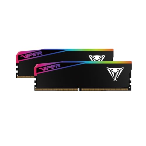
Patriot Viper Elite 5 Ultra RGB DDR5 RAM 32GB (2X16GB) 6000MT/s CL28 Memory
$209.99 · $6.56/GB · 32GB
In stock
Daisy chain topology (most modern boards)
In a daisy chain layout, traces connect from the CPU to Slot 1, then continue to Slot 2. Installing in Slot 1 and leaving Slot 2 empty creates a stub that reflects noise. Place sticks in Slot 2 and Slot 4 so modules sit at the end of each channel.
FIRST or 2 / 4 next to the recommended sockets.T-topology (legacy)
Older boards sometimes split traces equally to both slots on a channel (T-topology), favoring four-module configs. Modern boards — and every DDR5 four-slot board — use daisy chain instead. Even on T-topology boards, two sticks in 2 & 4 remain the common practice.
Placement performance implications
Frame-rate and boot stability across common layouts
| Configuration | Channel mode | Max stable speed | Gaming FPS loss | Recommendation |
|---|---|---|---|---|
| Slots 2 & 4 (A2 & B2) | Dual-channel | Maximum rated (e.g. 6000MT/s+) | 0% (full potential) | Optimal |
| Slots 1 & 3 (A1 & B1) | Dual-channel | Reduced OC stability (XMP/EXPO risk) | 1–5% (JEDEC fallback) | Suboptimal — avoid |
| Slots 1 & 2 (A1 & A2) | Single-channel | Stable but restricted | 15–30% (bandwidth limit) | Critical — fix layout |
| All 4 slots filled | Dual-channel (heavy load) | DDR5 often capped (~4800–5200) | 3–10% from speed caps | Only for capacity needs |
Related tools and guides
Motherboard memory layout FAQ
Why should I install RAM in slots 2 and 4?
Most modern motherboards use a daisy-chain memory trace layout. Traces run from the CPU through slot 1 to slot 2 (Channel A) and through slot 3 to slot 4 (Channel B). Installing in slot 1 instead of slot 2 leaves an empty stub that reflects signal noise and can break XMP/EXPO stability. Slots 2 and 4 terminate the traces properly.
What are the names of the RAM slots on a motherboard?
From closest to the CPU to the outer edge: Slot 1 (A1), Slot 2 (A2), Slot 3 (B1), and Slot 4 (B2). Channel A is A1/A2; Channel B is B1/B2. Dual-channel needs one stick per channel — the optimal pair is A2 and B2.
What happens if I put my RAM in slots 1 and 3?
You still get dual-channel, but empty terminal slots leave stubs that reflect electrical pulses. JEDEC speeds often boot; XMP/EXPO profiles at high MT/s frequently fail, blue-screen, or fall back.
What is the difference between single-channel and dual-channel memory?
Single-channel uses one data path; dual-channel doubles theoretical bandwidth. In games and CPU-bound apps, single-channel can cut frame rates by 15–30% and hurt 1% lows.
Should I fill all 4 RAM slots for better performance?
Usually no. Four sticks load the CPU memory controller hard. On DDR5, a board that runs two sticks at 6000 may struggle past 4800–5200 with four. Prefer a 2-stick kit in slots 2 and 4 unless you need the capacity.
How does an ITX motherboard differ for RAM slot planning?
Mini-ITX boards have two slots with short traces and no daisy-chain stubs. Fill both for dual-channel. They often overclock memory better than four-slot boards for the same reason.